It was a pain to solder surface mount parts on small boards and the hot air gun is annoying to use for really small parts and the reball machine was too big, enter the Solder Reflow Plate a Atmega 328p based reflow solution.
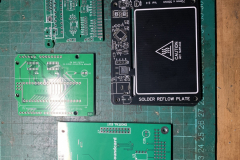
Reflow Plate PCBs
The project files can be found here and I used these gerber files to get the ATmega328p version and ordered them from JLCPCB. I opted for the black PCB’s for something different, it also helps with contrast of solder paste on it.
Building it up
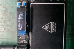
The soldering was fairly easy, just a few small 0402 passive components around the 328p chip that were a bit tricky. I had to hack in the little switches and a different package transistor as I ordered the wrong ones. I used a USBasp in circuit programmer and the Arduino IDE to program the device. The instructions found on the github here were:
Preparation
- Download and install the Arduino IDE from the Arduino Website. The sketch was originally developed on version 1.8.19, though any recent and all future versions of the Arduino IDE should be fully supported.
- Install the MiniCore additional boards to allow programming of bare Atmega (8bit) chips. Go to ‘File->Preferences’ and copy the ‘.json’ link below into the ‘Additional Boards Manager URLs’ textbox. If you have multiple sources, they must be separated by commas. https://mcudude.github.io/MiniCore/package_MCUdude_MiniCore_index.json
- Add the boards to the board manager by searching for and installing MiniCore in ‘Tools->Board->Board Manager’.
- Search for and install Adafruit_GFX and Adafruit_SSD1306 libraries in ‘Tools->Manage Libraries’.
Program
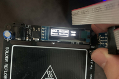
- Connect your programmer to the ICSP headers on the Solder Reflow Board. This can be any supported USBISP, USBasp, or even an Arduino programmed with Arduino as ISP. If using a commercial programmer make sure your drivers are installed. If using another Arduino make sure to upload the Arduino as ISP sketch and correctly connect the ISCP pins. Use this guide in the Arduino docs if you are unsure.
- Select the following settings under the ‘Tools’ tab
- Board -> MiniCore -> Atmega328
- Clock -> Internal 8MHz
- BOD -> BOD 2.7V
- EEPROM -> EEPROM retained
- Compiler LTO -> LTO Disabled
- Variant -> 328P / 328PA
- Bootloader -> No bootloader
- Set the programmer of your choice, e.g. ‘Arduino as ISP (MiniCore)’, ‘USB ASP’, etc, and set the correct port.
- Burn bootloader to the Solder Reflow Board. This sets fuses and registers correctly so that the sketch needs not directly deal with them.
- Compile and upload to the Solder Reflow Board.
Thermal tests
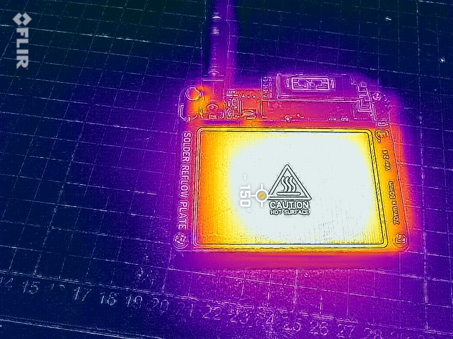
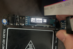
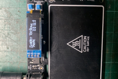
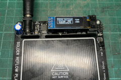
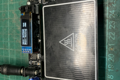
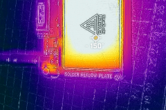
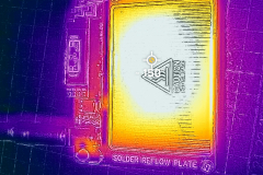
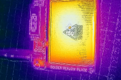
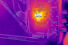
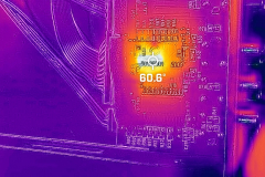
Just to verify that the board was working I did a quick test with my Flir iPhone camera, looks like to warms was well.

0 Comments