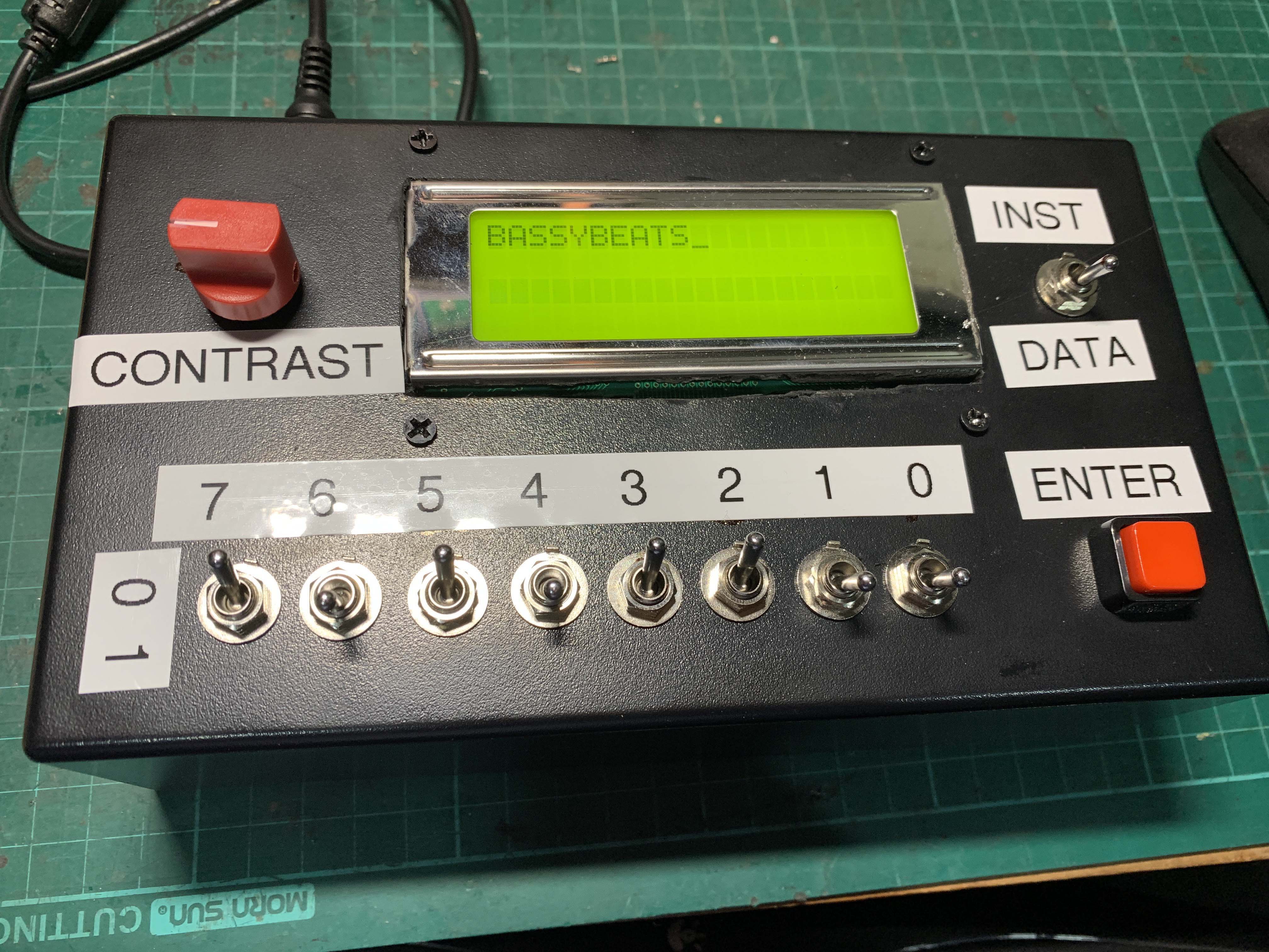
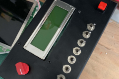
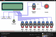
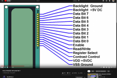
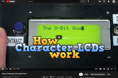
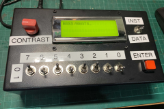
After seeing a video by the 8BitGuy on how an LCD Display works I remembered I had a bunch of 20×4 LCD screens sitting in a box and most of the parts and figured I could use some of these old parts up and make on one these boxes. I basically followed the tutorial in the video and wiring it up directly how he did.
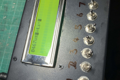
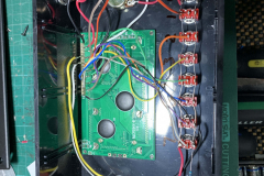
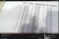
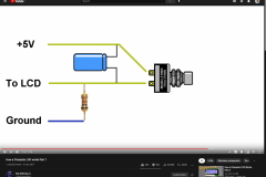
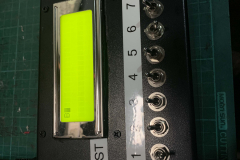
Wiring it up was pretty straight forward although I did run into a few issues that were explained in the video. I did not realise that binary numbers read LEFT to RIGHT, 7 to 0, not the other way around so Although I could get the capital letter B to work no other characters worked ( Capital B is the same backwards and forwards incidentally ). This is when I realised I wired it up backwards and had to reverse the switches left to right and make a new label. Another thing that was discussed in the video was the value of the resistor that pulls the enter switch to ground, I used a 100k resistor at first and realised it was too high, I then dropped it to 10k or 1k ( cant remember ) and tested the button and when you press the button it would over come the ground and give the switch 5V as expected.
So all in all a pretty cool little build and a cool little learning tool for understanding how binary works and how LCD displays work. Now I just have to remember all the 1’s and 0’s to make it work!





0 Comments