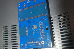
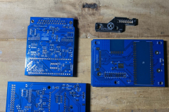
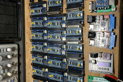
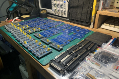
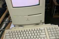
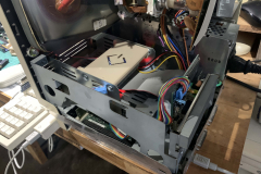
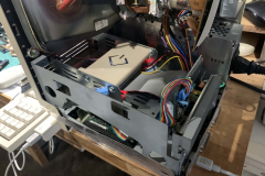
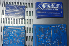
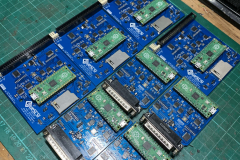
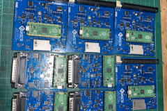
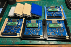
Down the SCSI rabbit hole I went when the drives in my Macintosh SE/30 and Macintosh Color Classic both died. I did a big order of V1 and V2 PCB’s on different occasions in the hope of making a bunch for my friends and community members which also covers some of my restoration projects.
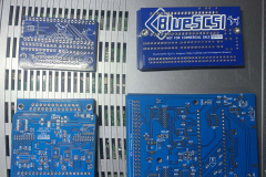
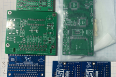
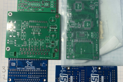
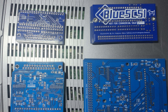
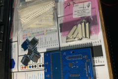
Ordering the PCB’s
The gerbers for V1 internal and external BlueSCSI’s can be found here https://github.com/erichelgeson/BlueSCSI
The gerbers for V2 internal and External BlueSCSI’s can be found here https://github.com/BlueSCSI/BlueSCSI-v2
Most of the parts I got came from AliExpress, Mouser and LCSC depending on where they were the cheapest or what else I needed to order. LCSC is the best to bulk order V2 parts as they had it all in one place. The BOM files are within the github CC-NC-HARDWARE folders.
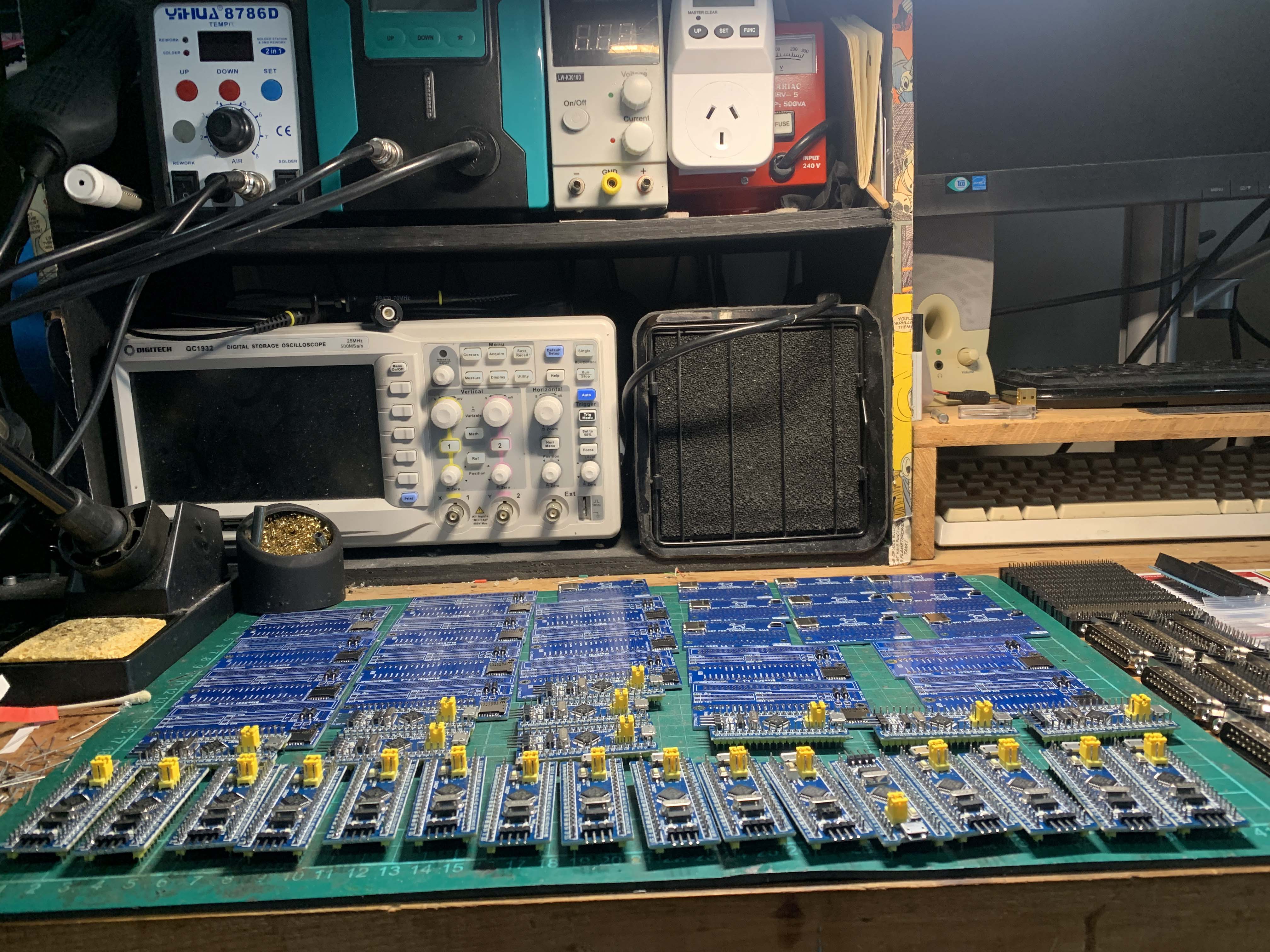
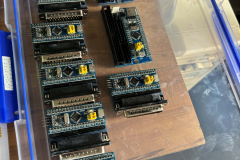
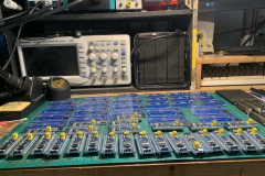
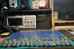
Soldering V1
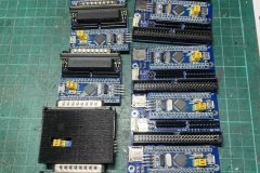
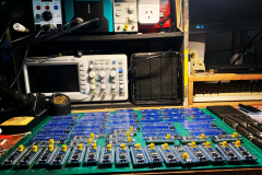
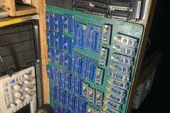
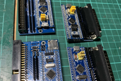
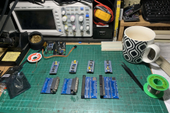
Soldering up the V1’s is by far the easiest of the two versions. I always started with the SD card slot. I at first I did it by hand but ended up doing it with hot air as I got confident to with the parts. Then the resistor packs and diodes and resistors. The STM32 Bluepill and pin headers went last. A trick I learnt with the jumper pins is to put a jumper on them and they don’t burn your fingers! All the boards got washed in 99% Iso afterwards before powering up.
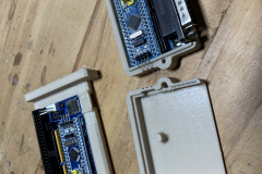
The 3D prints are here:
Programming and Testing V1
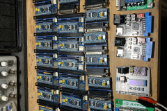
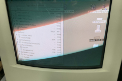
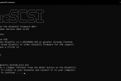
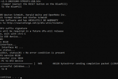
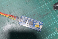
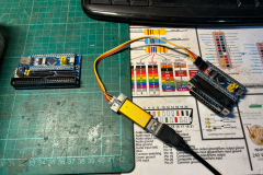
Firstly, definitely use the BlueSCSI Updater BAT file. It makes it so much easier. The releases for the STM32’s are here. To program them, I got a cheap ST-Link V2 programmer of AliExpress like this one, You can often get the BluePills at the same time. For the HDD image, I used the Macintosh Garden System 7.5.5 starter image and added a bunch of my own files, games and tests.
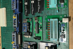
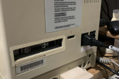
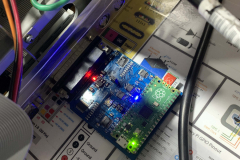
Programming went fairly well with only a few that I had to touch some soldering up on the SD card slots or a pin I missed. In the end I also made up some DB25 to IDC50 adapters to be able to test the internal drives externally.
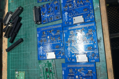
Soldering V2
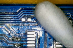
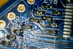
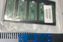
Soldering these was MUCH more painful. If you have never soldered 0402 resistors and capacitors, you don’t know soldering pain. I had so many issues doing this without solder paste, essentially doing it all by hand with a microscope, hot air and lots of flux. Ironically, the issues I had were with the SMD IC’s not the passive components which I had to go back over with and fix some bridges.
Programming and Testing V2
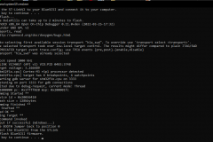
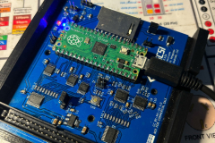
Programming the V2 was much much easier as the PICO only needs you to hold the rest button when you plug the USB cable in and it shows up as a flash storage device that you just drop the file onto, it then ejects it automatically once it is copied over. The releases are here.
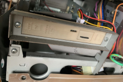
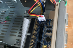
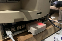
I opted for these cases as they screwed together. The internal one I went with these. I used the same image as the one I did on the V1 testing as it is all compatible.



0 Comments