As with a lot of my projects they seem to be long running and never get done. Well with the 2020 lockdown I had plenty of time to get through some projects, probably obvious by the volume of things I have been posting lately. Well this one was an idea I have had for a long time, it was based on the high volume of germanium transistors I ended up with from all my builds. Lots that were uncommon, out of ‘spec’ or not usually used in fuzz pedals.
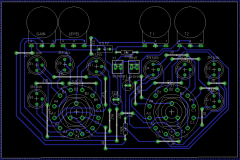
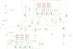
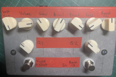
What I wanted was a way to load up 4 different options for Q1 and Q2 and be able switch between them all and bias them up externally by ear. The base of the project was a Fulltone 69 fuzz circuit as it sounded good and was easy to wire up. Initially, I wanted to have it negative ground so it can be used with normal power supplies from other pedals. I had a good crack at doing it in Eagle and making a PCB and never made progress or got it right, this was the part that delayed the project the most, holding onto the idea of a custom PCB.
The alternative plan
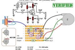
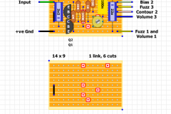
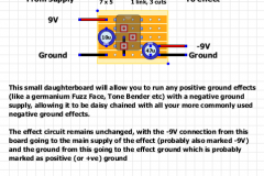
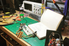
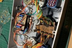
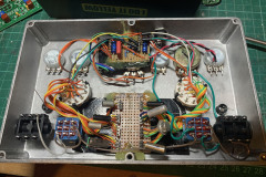
I eventually gave in hand wired a unit using 3 layouts from Tagboardeffects.com. The Fulltone 69 Fuzz, The Dallas Rangemaster and the Negative Voltage Inverter. These 3 circuits gave the options to wire it all by hand during the lockdown and get a working prototype working. If it works out and my friends want one as well I can then look at a PCB, but there was no point if it sounded like crap.
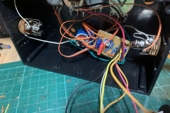
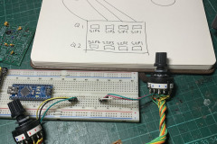
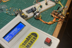
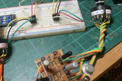
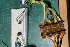
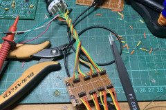
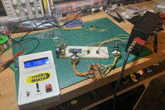
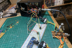
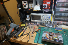
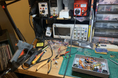
I actually already had a 69 Fuzz so it was just a matter of breaking out the trim pots and transistors onto a daughter board and the wire up some 4P3T rotary switches to change between each transistor for both Q1 and Q2. To test it out, I had to find a selection of PNP transistors that were roughly the right values to put in each spot, which I used my handmade transistor tester ( arduino based ). I actually left the sockets and patch wires on the fuzz board which meant I could still put transistors directly into it to verify issues if something didn’t work or stopped working.
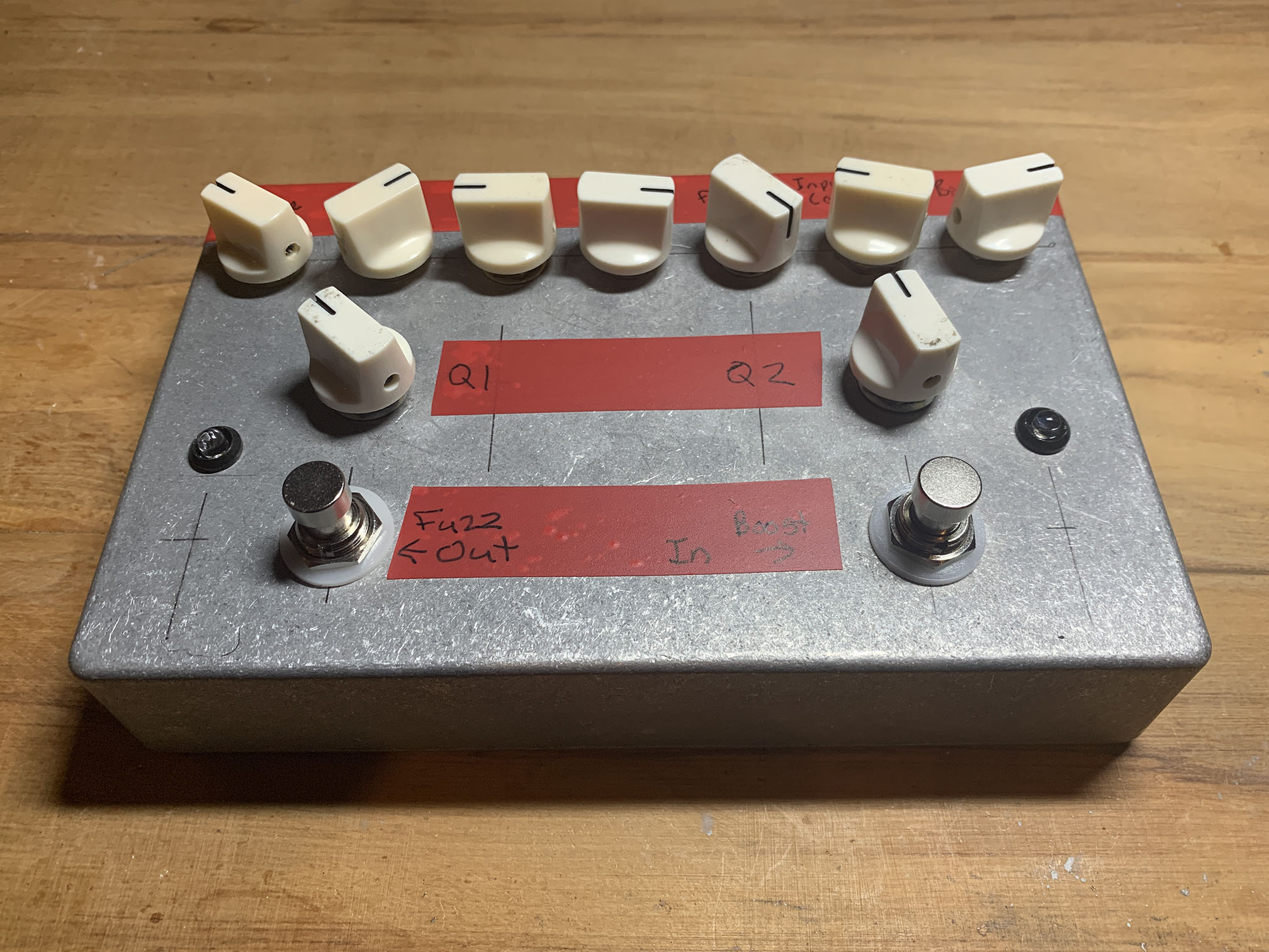
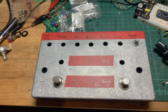
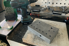
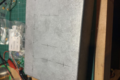
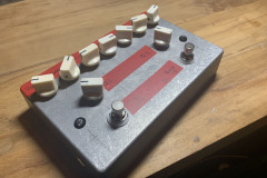
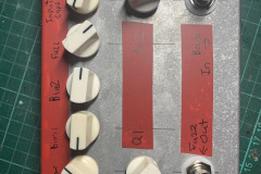
Next came figuring out how to box this whole thing up. It was going to be big, but I did have some old 1590DD cases that needed to be used, they aren’t good for foot pedals but are perfect for these testing units. Originally, I was going to do a voltage sag knob but after testing it out I instead changed to an input cap selector for the rangemaster.
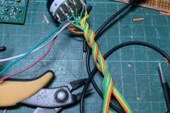
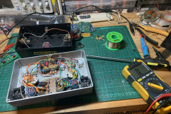
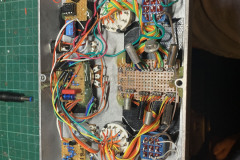
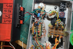
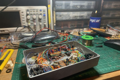
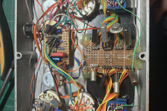
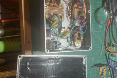
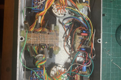
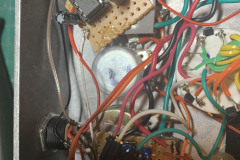
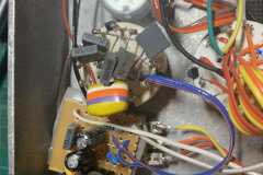
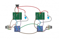
When it came to wiring it all together, it was a nightmare. The worst part of was getting the grounds all working fine and it is easy to get the LED’s and case grounds wrong. In the end I dropped my own versions and found the dual effect wiring diagram from MadBeanPedals.com. Once I got the switching working I only had some minor issues which ended up being a dead 7660S voltage inverter. Once that was solved it was just a matter of getting it all in the case together.
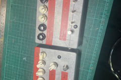
It all turned out pretty well and i’m surprised it actually works. I don’t think it will be worth making a PCB but I guess thats what vero/tagboard is for. It matches up well next to my other fuzz experiment box that has 3 different fuzzes + an LBP1 in it.

0 Comments