by bassybeats | Oct 28, 2023 | Others, Wood Working
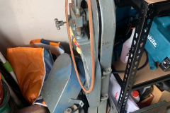
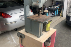
This bandsaw came from my grandads shed. Was completely falling apart and always tripped the breakers in the house. After 3yrs sitting in my sisters garage it was time to bring it back to life and put it back into service.
Starting Condition
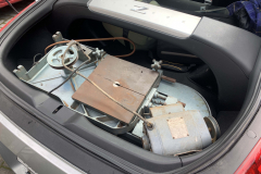
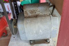
The starting condition was fairly rough, everything had a layer of rust, sawdust or grime on it. The first step was to break it down into its parts, clean it all and remove all the old bad wiring and grease. The old base was wooden and full of bora holes ( kinda like termites ). The whole thing got chopped up for firewood as I wasn’t going to be using it and it wouldn’t find in the car.
New Base
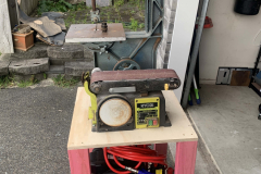
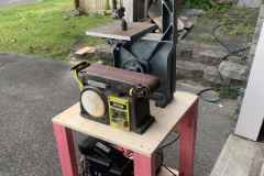
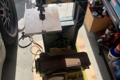
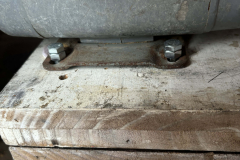
I knew I wanted the new base to be stronger and house more than just the bandsaw. I figured out that a 1200mm x 600mm x 18mm sheet of plywood would be perfectly sized to hold the bandsaw, belt sander and keep my small air compressor underneath, the only catch was that the motor had to be flipped / reversed for it to fit. The fasten everything together I opted to T-Nuts and bolts as this also made it easier to disassemble and maintain.
I originally went with 2x swivel wheels and 2x lockable straight wheels but immediately realised it was a nightmare to move around so I went for 4x lockable swivel wheels instead.
Full Rewire
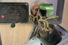
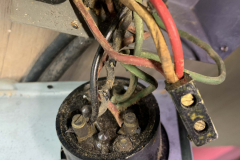
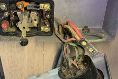
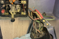
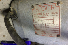
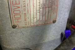
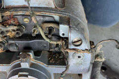
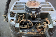
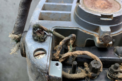
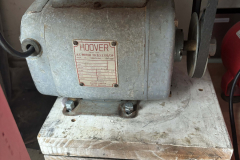
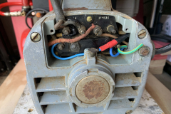
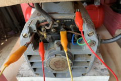
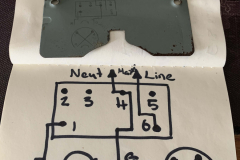
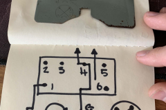
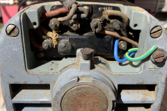
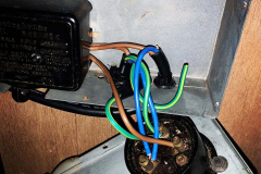
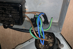
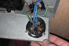
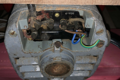
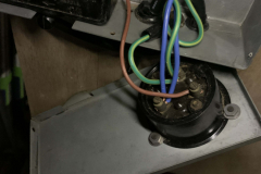
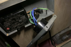
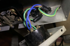
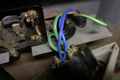
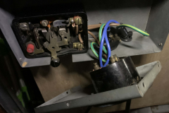
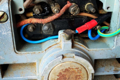
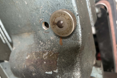
This was probably the hardest part of the whole project. To replace the wiring I ended up sacrificing old server power cables as they were long enough and heavy enough gauge. Wiring it was tricky but I eventually found that the wiring diagram was printed on the inside of the motor plate.
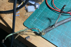
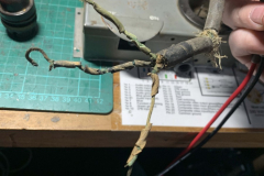
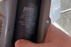
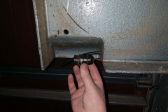
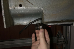
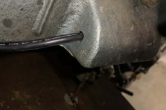
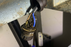
That wiring diagram also showed how to reverse wire it so the motor spun in the opposite direction which was great as I couldn’t find anything on the internet about this motor. As you can tell, the old wiring was frayed and corroded and in poor condition so it wasn’t a surprise that it use to blow all the fuses in the house.
New Blade
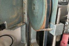
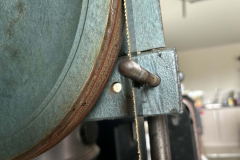
Getting a blade for this thing was much harder than expected. It turns out modern bandsaws use different blade sizes. The bandsaw has a fair amount of adjustment in it so I got the closest blade size of hardwood/soft metal I could find and made it fit.
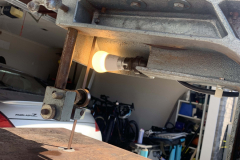
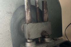
I had to remove the spring in the top adjuster to allow it to lower enough and I had to relocate and drill a new mounting hole for the front cover bolt. Now this thing cuts like butter, I just need to adjust some of the tension to remove some of the vibration.
by bassybeats | Oct 28, 2023 | Retro Gaming
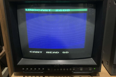
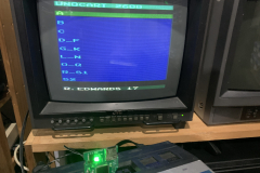
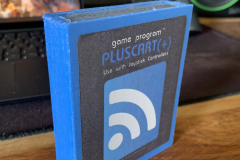
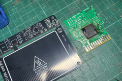
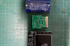
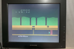
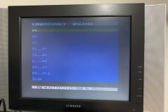
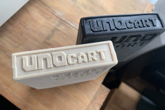
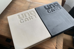
A quick and fast project to make a “multicart” for the Atari 2600. The UnoCart 2600 is an open source SD card based multicart for the Atari 2600.
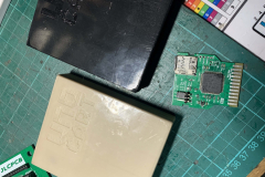
My build was based off UnoCart 2600 v1.03 project here on the PCBWay community projects. The project is based around the STM32F407VGT6/7 chips. Most of the parts are available on AliExpress or Mouser, the STM32 chip can be expensive to get if the stock is low. The soldering can be a bit tricky if you haven’t done hot air soldering before.
The programming can be done with the ST-LINK V2 via the pins on the PCB, I didn’t both with the pogo pins to program it. The firmware can be found here.
After than, it was just a matter of formatting an SD card as FAT32 and copied over a folder organised 2600 game library.
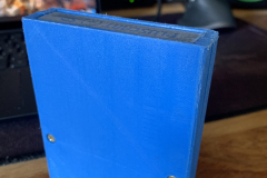
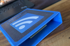
The STL files for the cases can be found here, they needed to be chopped/modded for this board to fit.
by bassybeats | Oct 18, 2023 | Retro Gaming
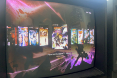
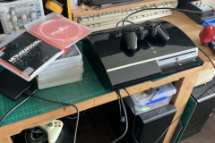
I never planned to get into PS3 but I ended up with a few, and specifically a Backwards compatible one. After I fixed the YLOD issues the next step was to CFW mod it and dump all my games so I can get rid of the physical copies I dont want, also means I can dump my PS2 and PS1 games to a single console.
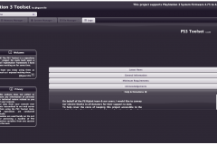
This whole process is based off this PSX Place CFW Guide and I would recommend using that guide directly not this post. At the time of doing this process PS3toolset was down so I had to use a Russian version of it, but the process is the same, you just have to use google translate to navigate the menus.
Prep work
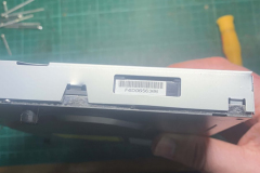
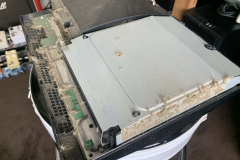
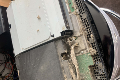
The prep work for both consoles was just a matter of stripping down the consoles, cleaning them out, installing a fresh 1TB HDD and a clean install of the 4.90 Official firmware.
CFW Installing
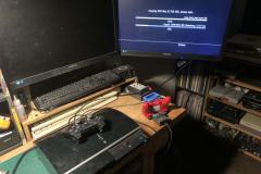
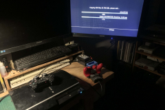
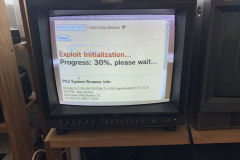
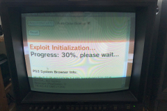
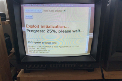
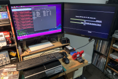
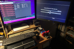
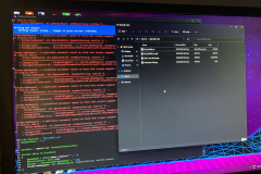
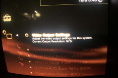
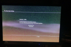
Again, I would use the BGToolSet process as it is the easiest. It took a few attempts to get it to exploit the system ( stated it is common on the page ). An issue that plagued me was an incompatibility with the LCD monitor I was running as it was all grainy, this was not present on a 1080p TV.
Pumping games and modding
Once the CFW was installed, I went and installed the standard tools like WebmanMOD, Multiman, Movian, Rebug_toolkit, IRISMAN etc.
Dumping the disc based games was fairly straight forward, you can dump them as ISO’s or as folders, both to the internal HDD or a USB HDD. Take note that the drive has to be formatted as Fat32 or exFAT.
If you are loading PSN games, you will need to find a patch the RIF files to RAP files. There is a 15,000 Rap file available on a Spanish blog that I won’t link to but you can RIF2RAP to do this as well. I opted to find the bulk set of RIF files and patch it to my system with a batch script.
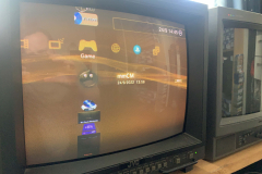
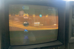
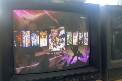
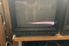
Once it was all loaded, it was fairly easy to use and I even got it all working with my 14″ Sony PVM!
by bassybeats | Oct 18, 2023 | Retro Gaming
Everyone has heard about the PS3 Tokin recap process, all I can say is that it is painful and I wouldn’t wish it on anyone.
Before
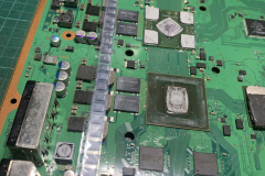
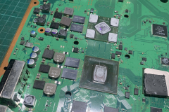
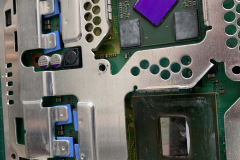
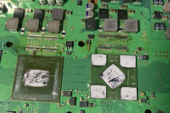
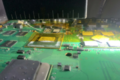
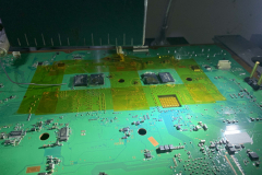
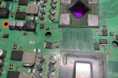
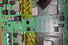
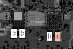
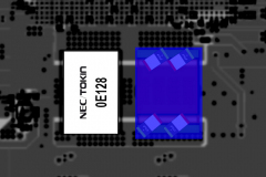
This was not the first time this PS3 has been stripped down to the motherboard. You can see that the CPU and RSX have been delidded and the thermal paste/compound has been replaced. This lasted a little while until it kicked another YLOD about 6 months later. My next point of call was to replace the notorious NEC Tokin caps. All of this was done before this video came out detailing a much better diagnosis process using the SYS_CON reading method.
Desoldering
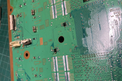
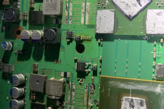
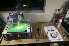
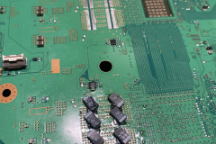
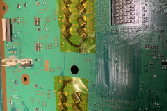
The desoldering process was not as straight forward as you would think, the PCB is so dense and so many layers a hobbyist soldering setup just can’t put enough heat into it. I ended up using my Reball station to pre-heat the board and then the caps came off fairly easily.
Fixing a mistake and after
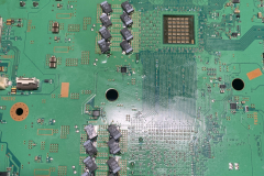
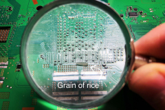
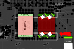
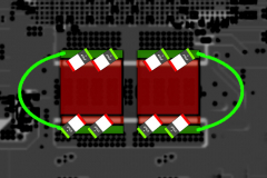
Adding the new caps was fairly straight forward. I just followed this guide from PSX-Place.com. One very annoying mistake I made when desoldering was I bumped a couple of the decoupling capacitors for the CPU which I think are 0201 sized which was extremely hard to fix, but I did fix it in the end.
After fixing my mistake the rest was easy, again you need to preheat the board to make it easier to put the new 470uf/6.3V tantalum capacitors back on. I did not leave the original NEC’s on so I had to make the bridging wires to replacing the internal bridging.
So far so good, the PS3 has been going well rock solid since doing this mod/fix.
by bassybeats | Oct 17, 2023 | Computing
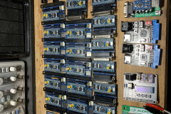
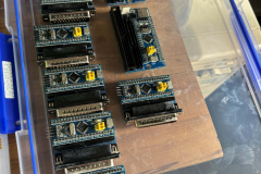
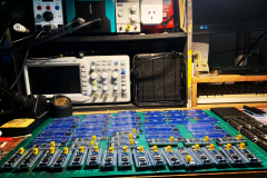
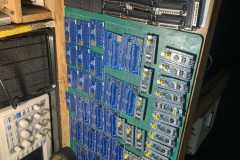
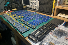
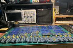
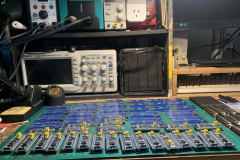
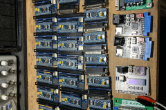
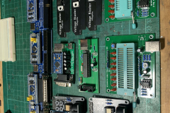
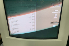
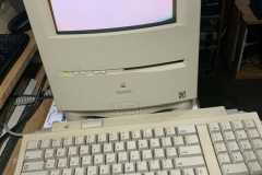
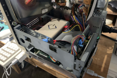
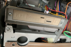
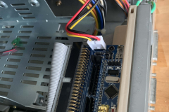
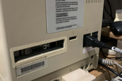
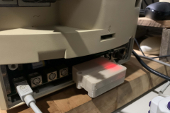
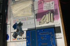
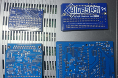
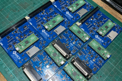
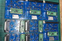
Down the SCSI rabbit hole I went when the drives in my Macintosh SE/30 and Macintosh Color Classic both died. I did a big order of V1 and V2 PCB’s on different occasions in the hope of making a bunch for my friends and community members which also covers some of my restoration projects.
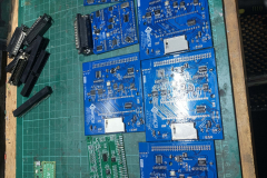
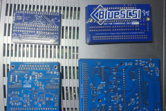
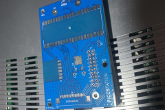
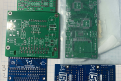
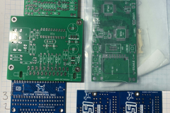
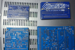
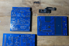
Ordering the PCB’s
The gerbers for V1 internal and external BlueSCSI’s can be found here https://github.com/erichelgeson/BlueSCSI
The gerbers for V2 internal and External BlueSCSI’s can be found here https://github.com/BlueSCSI/BlueSCSI-v2
Most of the parts I got came from AliExpress, Mouser and LCSC depending on where they were the cheapest or what else I needed to order. LCSC is the best to bulk order V2 parts as they had it all in one place. The BOM files are within the github CC-NC-HARDWARE folders.
Soldering V1
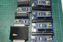
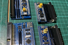
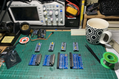
Soldering up the V1’s is by far the easiest of the two versions. I always started with the SD card slot. I at first I did it by hand but ended up doing it with hot air as I got confident to with the parts. Then the resistor packs and diodes and resistors. The STM32 Bluepill and pin headers went last. A trick I learnt with the jumper pins is to put a jumper on them and they don’t burn your fingers! All the boards got washed in 99% Iso afterwards before powering up.
The 3D prints are here:
Programming and Testing V1
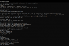
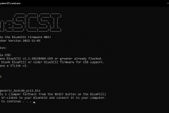
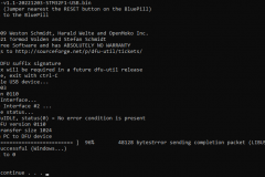
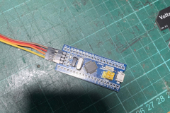
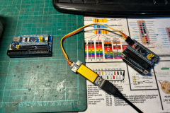
Firstly, definitely use the BlueSCSI Updater BAT file. It makes it so much easier. The releases for the STM32’s are here. To program them, I got a cheap ST-Link V2 programmer of AliExpress like this one, You can often get the BluePills at the same time. For the HDD image, I used the Macintosh Garden System 7.5.5 starter image and added a bunch of my own files, games and tests.
Programming went fairly well with only a few that I had to touch some soldering up on the SD card slots or a pin I missed. In the end I also made up some DB25 to IDC50 adapters to be able to test the internal drives externally.
Soldering V2
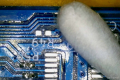
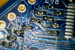
Soldering these was MUCH more painful. If you have never soldered 0402 resistors and capacitors, you don’t know soldering pain. I had so many issues doing this without solder paste, essentially doing it all by hand with a microscope, hot air and lots of flux. Ironically, the issues I had were with the SMD IC’s not the passive components which I had to go back over with and fix some bridges.
Programming and Testing V2
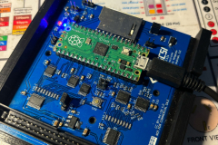
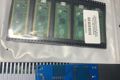
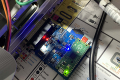
Programming the V2 was much much easier as the PICO only needs you to hold the rest button when you plug the USB cable in and it shows up as a flash storage device that you just drop the file onto, it then ejects it automatically once it is copied over. The releases are here.
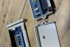
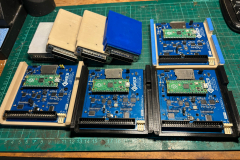
I opted for these cases as they screwed together. The internal one I went with these. I used the same image as the one I did on the V1 testing as it is all compatible.



Recent Comments